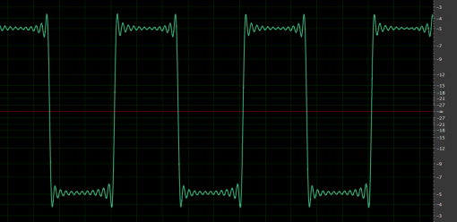
 Dixie II 1kHz square wave
Digidesign 192 @ 48kHz
[/one_half]
[one_half_last]
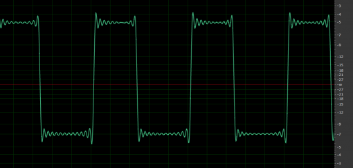 Z3000mkII 1kHz square wave
Digidesign 192 @ 48kHz
[/one_half_last]
Hmm... that's interesting. Looking at it, you might think you see tons of overshoot and a fair amount of ringing. If you were to leave it at that, you might be unimpressed. However... Let's think about what we are actually testing: There's a VCO, a balanced driver, and an ADC in this system. What is the VCO spitting out? My first guess would be a square wave whose signal is only band limited by whatever limitations are inherent in the circuitry itself. Meaning that no explicit filtering has been done - and why should it? This is analog! The signal bandwidth runs out into the nether regions of dogs and bats - and on. Okay, so then theres the 'io module. Is that ringing due to the 'io? That's a possibility, and perhaps I'm biased, but let's assume that no, our fancy schmancy nw2s::io isn't going to do that to your signal. The Digidesign 192? Do you know how many records were recorded and mixed on a Pro Tools HD system? This is proven technology... period. Even the haters can't honestly say that every album recorded and mixed on an HD system sounds like crap. Just to be sure, let's try recording a signal that comes from the square wave generator in our DAW. It will be band limited by definition since it's starting digital and ending up digital.
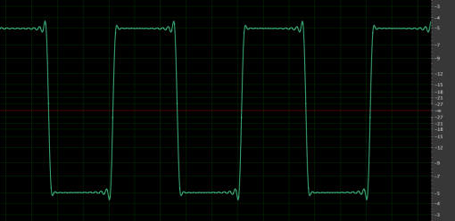 Interesting. It's still got some ringing, but it's significantly reduced and most of the ringing occurs prior to the falling edge...
Wait - How can the ringing start BEFORE the falling edge? And what IS that ringing?
Spoiler alert: It's the antialiasing filter on the Digidesign 192.
If you look at those screen shots again, you will see that there is not only ringing, but in all cases there is PRE-ringing. There is only one way in the physical realm we currently occupy to achieve pre-ringing, and that is using a digital filter. Specifically, one that oversamples the signal and decimates to optimize for phase response near an extremely sharp cutoff frequency.
There's a lot of math in those few sentences that may not be immediately evident, so I'll just let that settle for a bit.
The important thing to note is that of all the ringing that we just measured (not to mention a significant portion of the rise and fall time) is likely due to our ADC interface. And that even though it looks extreme, it actually doesn't sound bad at all and is there for a very good reason.
If you change the sample rate to 96 or 192kHz, the shape of the ring will change - but it won't go away completely. Here's the Z3000 going through the 'io and into a 192kHz session: (It's still 1kHz, but zoomed in to see the higher frequency ringing)
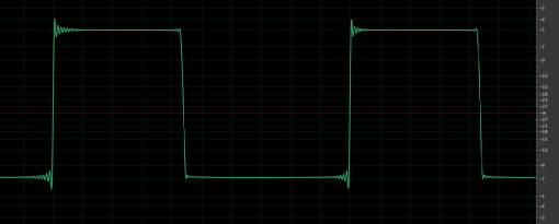 What's happening is that we're sending a crazy signal with harmonics reaching the atmosphere into a system that has to get rid of them to avoid aliasing when converting to a discrete (digital) signal. You're going to get some ringing. The ringing will be reduced when you increase the cutoff frequency, and this is the primary argument for recording at a 96kHz rate over 44.1kHz. The filter is better behaved in the frequencies we can actually hear.
### What do we do now?
So we haven't really proven anything yet. Even at 192kHz, we're seeing ringing. We're going to need something other than an audio interface to analyze the performance of our I/O modules. This is what oscilloscopes were invented for. I have a very basic Tektronics digital scope that will store files on disk. The screen shots are tiny, but the values can be saved as CSV and graphed in your favorite spreadsheet. Even then, this thing is meant to be more of a diagnostic tool than a lab device.
Here's What the Z3000 looks like going directly into the Tektronix. The Tektronix samples at 1GS/s with a resulting bandwidth of 50Mhz. (a lot higher than our audio interface that has a bandwidth closer to 20kHz)
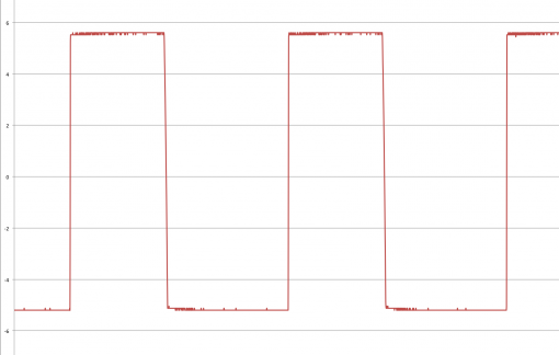 You can tell that now there's no ringing. There's some noise in the LSB, but that's probably due to the ADC stage. You can also tell (looking at the data, not the graph) that the rise time is about 3µs. Knowing that the rule of thumb for calculating the bandwidth of a square wave by its rise time is
[latex]BW = \frac{0.35}{RT}[/latex]
we can calculate that our Z3000 creates a 116kHz signal. From the data, I can also tell that there is no ringing and no overshooot. Only some noise in the LSB of the digital oscilloscope. [table] time (seconds), voltage 0.000979, -5.2 0.00098, -5.2 0.000981, -5.2 0.000982, -5.2 0.000983, -5.2 0.000984, -5.2 0.000985, -5.2 0.000986, -5.2 0.000987, -5.2 0.000988, -5.2 0.000989, -5.2 0.00099, -5.2 0.000991, -5.2 0.000992, -5.2 0.000993, -5.2 0.000994, -5.2 0.000995, -5.2 0.000996, -5.2 0.000997, -5.2 0.000998, -5.04 0.000999, 1.12 0.001, 5.52 0.001001, 5.52 0.001002, 5.52 0.001003, 5.52 0.001004, 5.52 0.001005, 5.52 0.001006, 5.6 0.001007, 5.52 0.001008, 5.52 0.001009, 5.52 0.00101, 5.52 0.001011, 5.6 0.001012, 5.52 0.001013, 5.52 0.001014, 5.6 0.001015, 5.52 0.001016, 5.52 0.001017, 5.6 0.001018, 5.52 [/table] Okay, so now we wil take a measurement of the output of the 'io. Now that we are using pokey probes instead of audio connectors, we need to know where to take the measurement. I connected a DB-25 to XLR snake to the output and measured between the two active pins (pins 2 and 3), ignoring the ground - which is what makes a balanced signal. Here's the graph: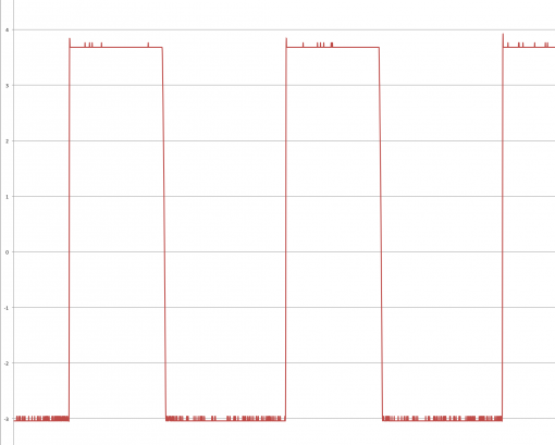 And here's the data from one of the rise phases.
[table]
time (seconds), voltage
0.00098, -2.96
0.000981, -2.96
0.000982, -3.04
0.000983, -3.04
0.000984, -3.04
0.000985, -3.04
0.000986, -2.96
0.000987, -3.04
0.000988, -3.04
0.000989, -3.04
0.00099, -2.96
0.000991, -3.04
0.000992, -3.04
0.000993, -2.96
0.000994, -3.04
0.000995, -2.96
0.000996, -3.04
0.000997, -2.96
0.000998, -3.04
0.000999, -2.16
0.001, 1.12
0.001001, 3.6
0.001002, 3.92
0.001003, 3.68
0.001004, 3.68
0.001005, 3.68
0.001006, 3.68
0.001007, 3.68
0.001008, 3.68
0.001009, 3.68
0.00101, 3.68
0.001011, 3.68
0.001012, 3.68
0.001013, 3.68
0.001014, 3.68
0.001015, 3.68
0.001016, 3.68
0.001017, 3.68
0.001018, 3.68
[/table]
So we can tell that the rise time is still about 3µs and the bandwidth is about the same. There is some noise in the LSB still, but still no measurable ringing. The only difference is a slight blip of overshoot on the rising edge about -30dB down that lasts only about 1µs. Before, I said that overshoot and ringing are typically cause by band-limiting filters, right? The 'io has no filtering in it... and the Tektronix does, but way out in the 50Mhz range. Where could that be coming from?
A low-pass filter is nothing more than a capacitor in parallel and/or an inductor in series. Optionally, a gain stage can be added to compensate for loss. The system itself is a filter. The balanced driver is a gain stage and the 10 foot DB-25 cable contains capacitance between the wires as well as inductance in the twists. The THAT 1606 is made to drive loads far less well behaved than my cable, so this is where our tiny bit of overshoot is likely coming from. Nothing's perfect - you'll never get around the limitations of physics, but you can count on the fact that most devices have been designed to be well behaved in the face of adversity.
### That's it?
So there you go. This is as good as I can get with the tools I have a available which is more than average, but nowhere near the best.
What's the takeaway?
Know what different tests measure
Know the limitations of your tools
Know what the components of your system are
And lastly...
Listen.
Oh, and...
Make music.
